Name: Shah Asaduzzaman
ID: 260011168
E-mail: asad@cs.mcgill.ca
Name: Zaki Hasnain Patel
ID: 110029524
E-mail: zpatel@cs.mcgill.ca
2 versions of the project is sumitted. Each of them include one of the 2 diferent implementations of the channel.
tcp.des [top level model]
TCPDriver.des [TCPDriver]
Channel.des [Channel]
ClientApp.des [Client Application]
ServerApp.des [Server Application]
Scheduler.des [Scheduler model, re-used from
the Thomas Feng's chat software, slightly modified]
c2sout.txt [a sample output file, activity of
the c2s channel]
s2cout.txt [a sample output file, activity of
the s2c channel]
Datagen.des, Notifier.des
[2 simple models used for component debugging, not part of the final model]
tcp.des [top level model]
TCPDriver.des [TCPDriver]
Channel2.des [Channel - alternative implementation]
ClientApp.des [Client Application]
ServerApp.des [Server Application]
Scheduler.des [Scheduler model, re-used from
the Thomas Feng's chat software, slightly modified]
c2sout.txt [a sample output file, activity of
the c2s channel]
s2cout.txt [a sample output file, activity of
the s2c channel]
Datagen.des, Notifier.des
[2 simple models used for component debugging, not part of the final model]
A simple java program that produces a graphical event trace output from the
text output files generated by the simulator
Plotter.java [main program]
LinesFrame.java [required frame class]
The original visio drawings [.vsd] are available in this directory
presentation.ppt
presentation.pdf
Objective of the project is to simulate the reactivity of a software agent that speaks TCP or Transmission Control Protocol to a peer similar agent, and demonstrate the event-trace over time. To facilitate the simulation we have devised a complete communication scenario which is described in the Total system section. TCP works over IP. We haven't implemented the complete TCP, we were to demonstrate the connection management scenario only.
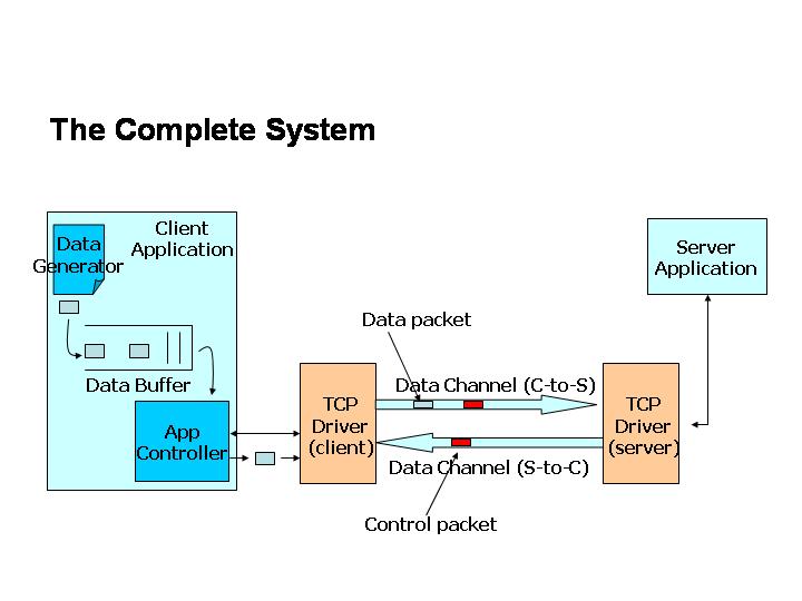
The complete scenario devised to demonstrate the activity of a TCP agent is shown in the following figure.
The Client application has a automatic data generator which actually generates dummy TCP sessions with randomly distributed IAT (exponential distribution) and randomly distributed data size (geometric distribution). Idealy there should be a 'connect' API call to the TCP driver as soon as a session is requested. Normally operating system provides a mechanism to block the application until the TCPDriver is in available (or closed) state. Otherwise, in terms of statechart symantics, what happens is that the connect API call will be discarded by the driver. To compensate for the operating system blocking mechanism, we have introduced a buffer between the TCP driver and the data generator. There is a controller that keeps watching the bufer and generates necessary API calls to the TCP driver.
The server application is simple which just keeps listening to the connection. It may occassionally fail according to an exponential distribution of MTTF (mean time to fail)
There are 2 peer TCP drivers, one in each of the client and server side. TCP drivers are the software agents that speak TCP protocol. They are directly implemented using the TCP specification state-automaton [please see the TCPDriver statechart or details].
TCP drivers talk to each other through a communication channel that works on
IP (Internet Protocol). We abstracted all the complexities of the channel and
modelled it as a pair FIFO pipes. 2 pipes are used to model the full-duplex
nature of the channel. We have assumed lossless communication because, the TCP
connection management state-automaton doesn't take care of retransmission. There
is a limitation of modelling the channel using statecharts, because the channel
basically has a large number of states as its bandwidth grow. This issue is
discussedin the statechart desion section for the channel.
The Transmission Control Protocol (TCP) orks in the transport layer of a computer netwrork system and provides reliable connection oriented comunication serice to the user application. The underlying service that TCP uses to provide this connection oriented service is teh raw, unreliable packet delivery service of IP. TCP establishes a connection using 3-way handshaking protocol, then transmits the data in ordered manner and then upon application request, releases the connection. We have demonstrated the conncetion establishment and release phases of a TCP agent. Please see the TCPDriver statechart design for a etail view of the TCP behavior.
We have chosen statecharts for modelling the system, because TCP connection management is a reactive system, and we basically wanted to observe the behavior of the system in case of various events. We were not concerned with any long term system performance statistics. That's why statechart model best suited our purpose.
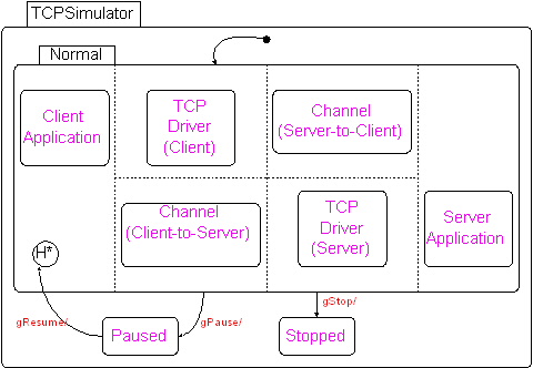
As visualized in the block diagram of the total system, it is easy to realize that the total system has 6 orthogonal components at the topmost level - a client application, a server application, 2 TCP drivers each connected to one of the application and 2 simplex channels that costitute a full-duplex channel. The top level statechart shows these components.
The following figure shows the top level statechart. We kept 2 states Paused and Stopped to control the simulation with external events. The Channel and TCP driver components are re-used with necessary macro parameters
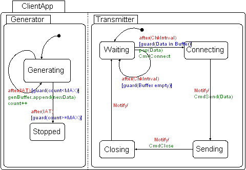
The client application has 2 orthogonal components. This is made just to make sure that not generated data is lost. The genarator generates data and put it in the buffer. A controller actually issues the system calls necessary to create/manage the tcp conections and send the data. The statechart is as follows.
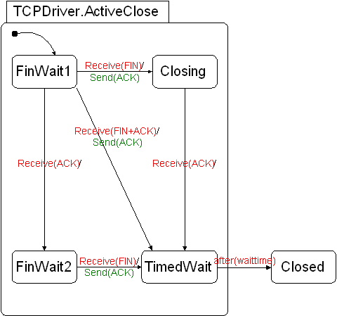
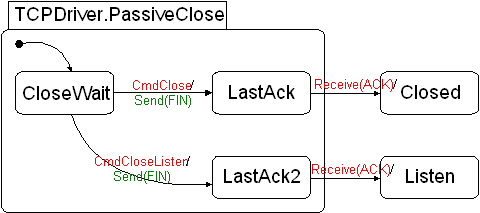
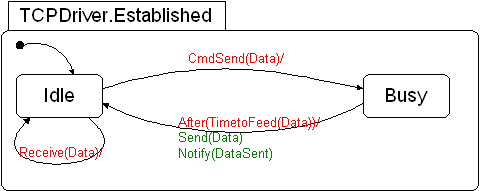
TCPDriver, the core component of the system actuallly implements the TCP protocol (connection management part). It is basically taken from the TCP state machine definition. For modularity, we tried to model is a bit structurally. The same TCPdriver can work with both the client and server type application, but for each clint or server one driver is needed.
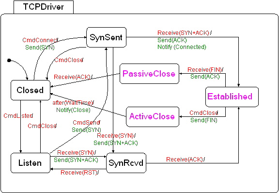
The PassiveClose, Established and the Active Close components are elaborated below. Actually ActiveClose and PassiveClose is not totally modularized, because each of them has outgoing transition form particular internal state to a state outside the component. Established is completely modularized in that sense.
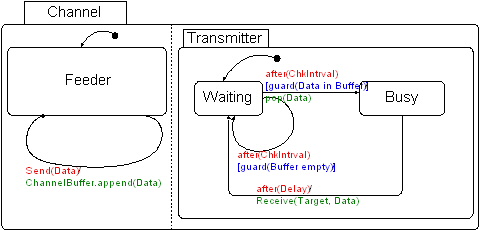
Now comes the channel. The channel is modelled as simple as possible as a FIFO and lossless channel. To simplyfy further, it is assumed that only one data segment can travel thru the channel at a time. That implies a very limited bandwidth of the channel. Technicaly it is possible to introduce sevral stages in the channel an represent them with states, but that complicates the model and we didn't go that way because that was not our purpose.
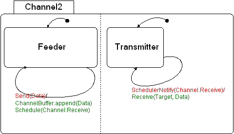
An alternative model of the channel is also submitted as Channel2, which actually takes advantage of the event scheduler that was explicitly modelled to implement virtual time simulation in contrast to real time one. But this model behave much more realistically than the earlier one. Actually it is a limitation of statechart/finite state machine that doesn't allow modelling system with infinite number of states. Benow is the statecharts of channel and channel2
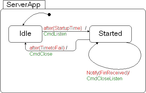
The server application is simple. It calls the Listen API, when it starts and remains in the listen mode. Here we did a little twist in the protocol, to keep the server alive after a datatransmission ends and conectin is closed from the clisent side. Actually, the server acts in such a way that after closing the connection it goes back to Listen state instead of going to closed state. The server also has a time to live before it fails. When the server fails, it closes the connection in whatever state it is, and the TCPdriver actually goes back to the closed state.
For implementation of the project we used the Statechart Virtual Machine developed by Thomas Feng in MSDL, SOCS, Mcgill university. The .des files are manually created althought the visual assistance tool AToM3 was available. For ease of debugging, sufficient number of print messages are i ncluded, so that the actual progress of the simulator can be monitored. The SVM currently can run the statescharts in real time. For running the statechart as a simulation in virtual time, an explicit model of a event scheduler had to be used. We tested the program with the SVM debugger currently available.
We used several new features of SVM version 0.3 extensivlely, such as parameterized events and importing sub-models. Importation actualy aided the re-use of our Channel and TCPdriver components
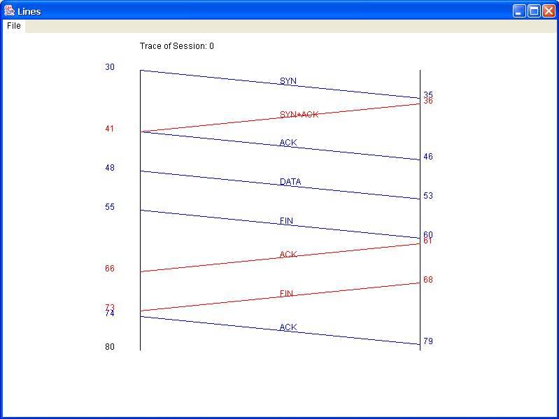
Here we include some traces of the simulation and represent it graphically. For graphical representation , we also developed a small program that can read the text file outputs generated by the simulator and can produce graphical event traces.
You can invoke the program as -
java Plotter <c2s-outputfile> <s2c-outputfile>
Th plotter plots the event trace of one session at a time. Press space bar to scroll over the different sessions.
Here is a sample screenshot of the Plotter.